Faculty of Science, Technology and Medicine
 Faculty of Law, Economics and Finance
 Faculty of Humanities, Education and Social Sciences
 Interdisciplinary Centre for Security, Reliability and Trust
 Luxembourg Centre for Systems Biomedicine
 Luxembourg Centre for Contemporary and Digital History
 Luxembourg Centre for European Law
 Luxembourg Centre for Socio-Environmental Systems
Structural concept
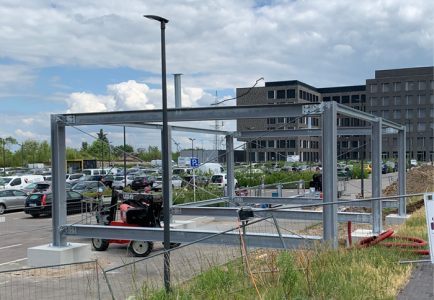
The structural system of the “Petite Maison” was developed based on the findings of a research project entitled “REDUCE – Reuse and demountability using steel structures and the circular economy” which was funded by the Research Fund for Coal and Steel (RFCS) with Grant Agreement No. 710040. Both investigations of “REDUCE” and “Petite Maison” targeted the development and demonstration of circular, demountable, and reusable structural elements and systems for a circular economy.
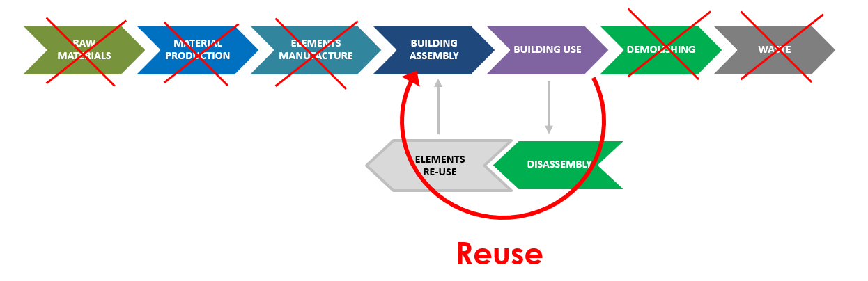
Ideally, a structural system should be designed in a way that is easily demountable with its elements reusable in a wide array of use applications (commercial, office, multi-storey) over multiple reuse life cycles. A considerable reduction of greenhouse gas emissions may be achieved from the development and wide adoption of reusable structural elements and systems, with the promotion of the European Green Deal and the Taxonomy Regulation in the construction sector.
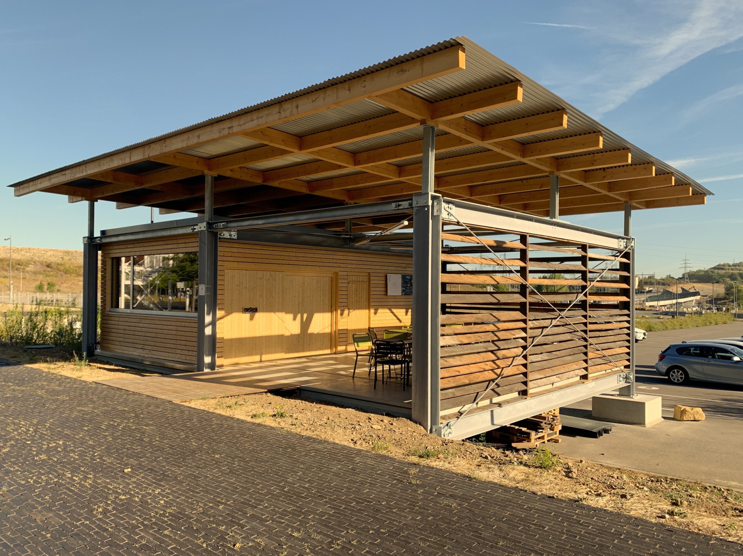
The design of the structural system of the “Petite Maison” has considered important factors identified for design for deconstruction and reuse. The design philosophy was, to separate the main structure into elements of steel columns, steel beams, precast concrete slabs, to assemble these elements onsite and later disassemble them for reuse elsewhere. These elements should be suitable for transportation and lifting with a usual crane, and the assembly and disassembly process should be easy and fast. In a functional unit “floorings system” of the designed structure, beam and slabs are assembled with demountable and replaceable bolts as shear connectors. Columns and beams are linked with adjustable steel connections. Other parts of the structure like timber roofing and the walls should also be demountable. When the function of the building with demountable and reusable systems is to be changed; or, the building is finishing its service life, it will be deconstructed, and the elements must be checked for integrity. They can be used elsewhere in another construction project afterwards.
The objectives of the “Petite Maison” project were:
- to realize the concept of circular, demountable, and reusable construction in a pilot project,
- to design a completely demountable and reusable building structure and design the elements in a way that maximizes their potential in reuse,
- to propose and organise a system of “Structural KITs
- to investigate the suitability of links between each element and their virtual database to facilitate reuse, tracking, storage of geometry, loads, use history data, and
- to demonstrate three phases of the structure, namely construction-, use- and deconstruction phase, and relevant findings of the RFCS Research Project “REDUCE”.
“REDUCE” investigated methodologies, tools, and guidance to assist in design for deconstruction and reuse, particularly of composite steel structures for multi-storey buildings. The outcomes should lead to new constructional methods and design configurations including connection systems for demountable composite construction, based on (i) numerical simulations, (ii) laboratory test campaigns, and (iii) analytical investigations including methods to predict load bearing capacities and deformation behaviour. The quantification of whole life benefits of structures using the developed demountable and reusable systems were performed in this project, using Life Cycle Assessment and circular economy indicators. Opportunities for greater standardization and the use of BIM were explored to facilitate disassembly and reuse instead of demolishing and recycling and/or downcycling. A demonstration of demountability of the developed system was planned as well as guidance on design for deconstruction and reuse.
During the project phase, it was identified that a system for easy disassembly and reuse must consider the following factors. This leads to the development of reuse of functional structural elements like beams, columns, floor slabs, and the considerations of prefabrication and sizing of these elements for (dis)assembly, lifting and transportation.
- The design must, as far as possible, follow the normal structural guidelines, for example the Eurocodes. It should differ from the codes only where absolutely needed.
- The design must close the loop as tight as possible.
- The structural system should be robust, demountable, modular, standardised, and with structural grids that respect a standard module size. This could be for example a grid that that is based on the multiples of 1.35 m or 1.5 m.
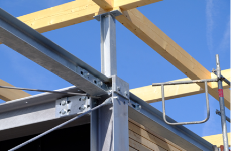
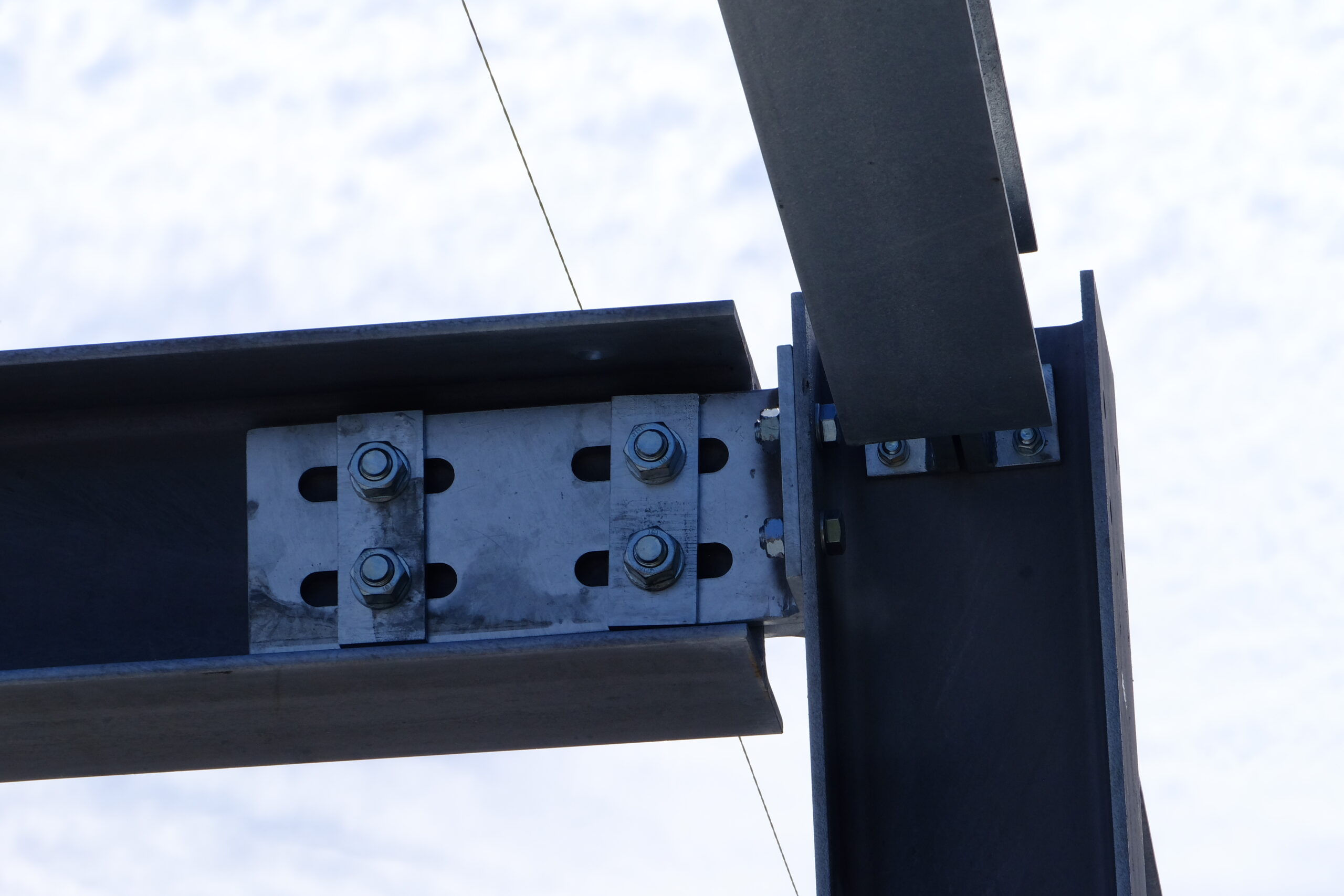
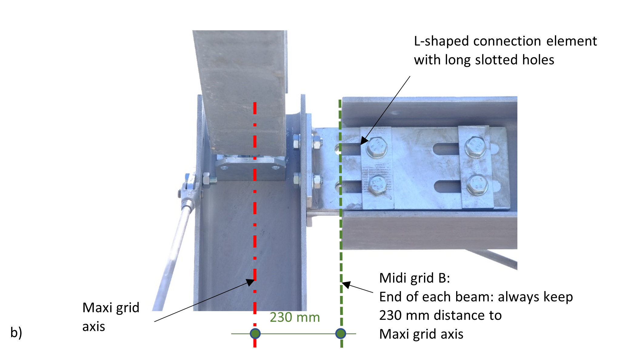
The KIT “steel beam” with steel joint, designed for adjustability, demountability and reusability
The system uses standardised nominal beam lengths that are suitable for a wide range of supporting members within the same planning
grid. At the ends of the beam L-shaped connection pieces are provided with long slotted holes. These allow to push and draw back the
connection element to fit and connect with supporting members with different dimensions. This makes the beam extendable; and therefore,
its length adjustable.
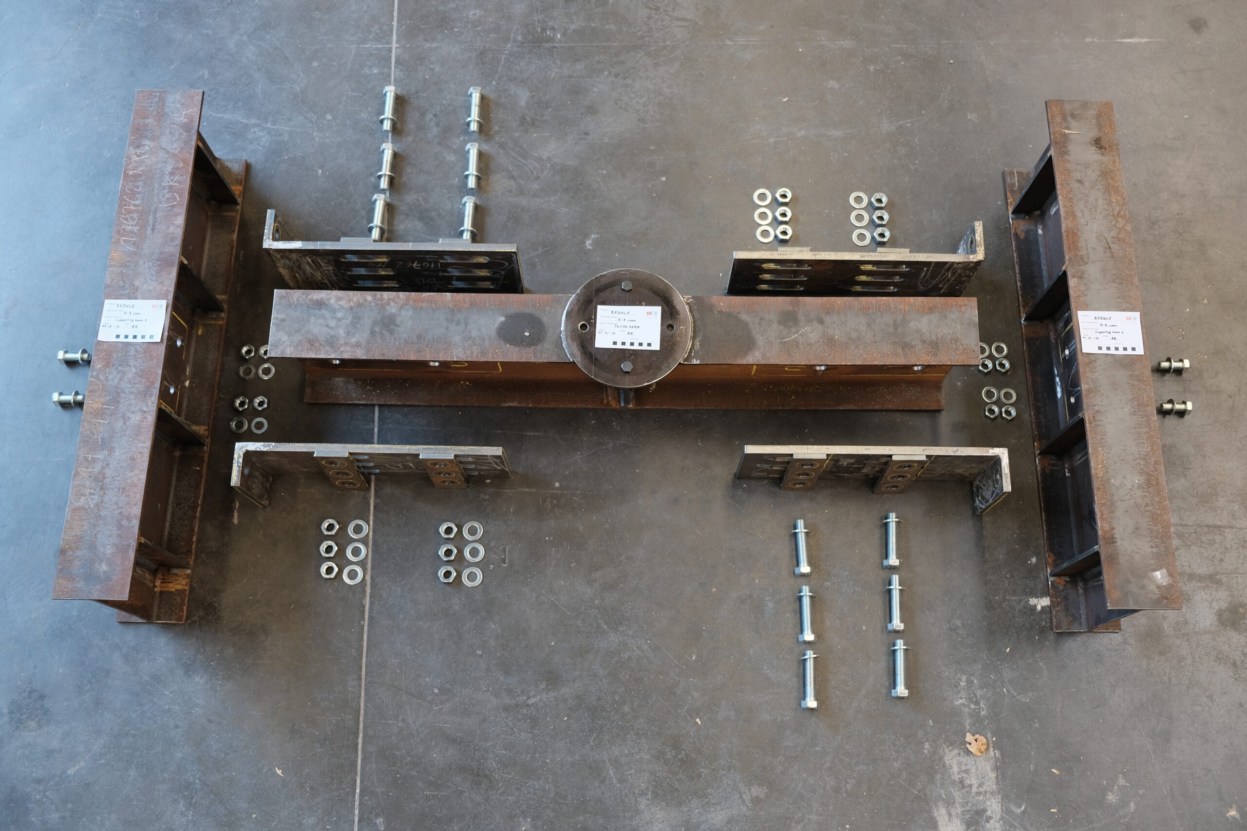
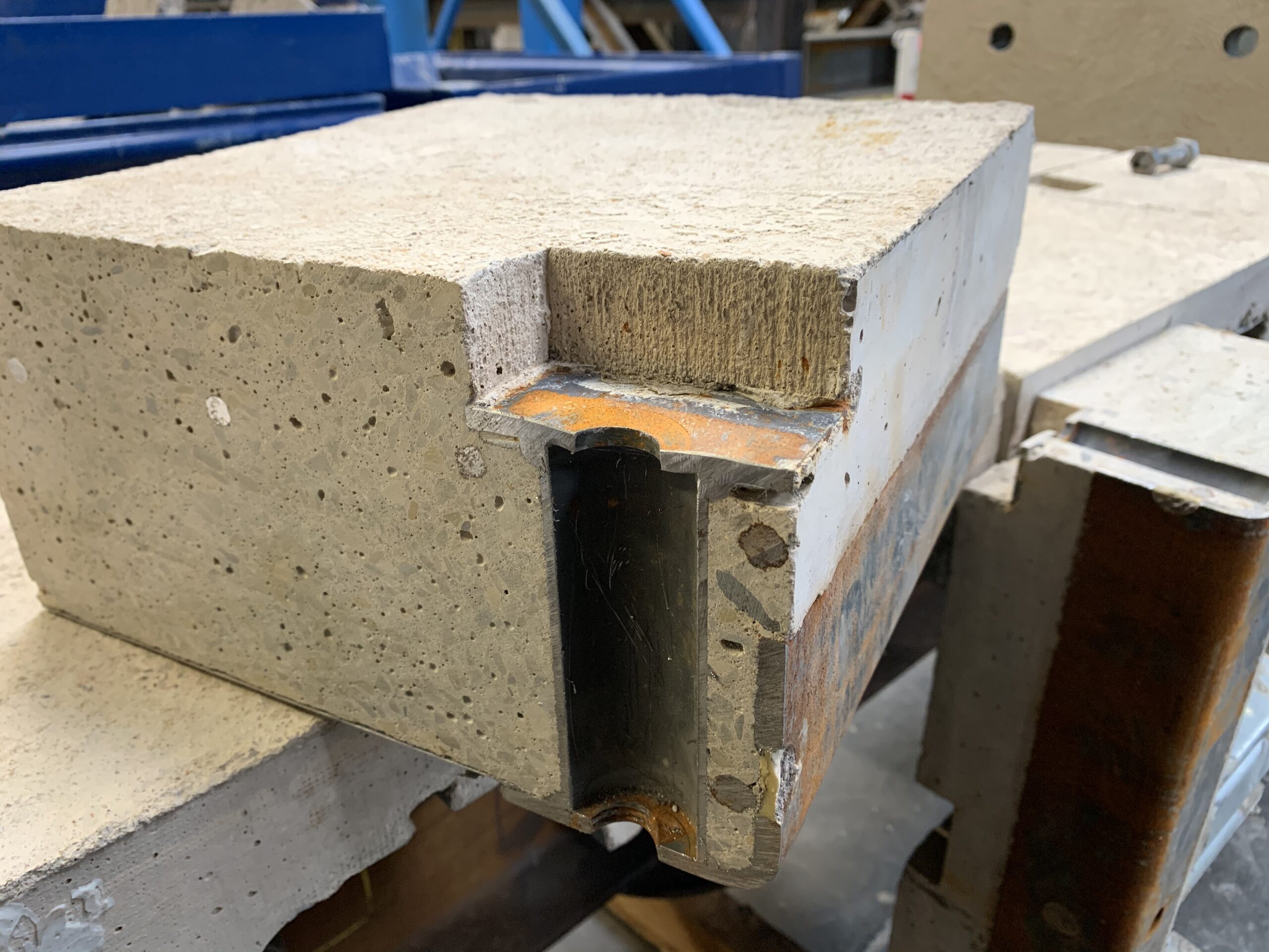
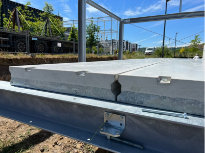
The KIT “concrete slab element”, designed for demountability and reusability”
The concrete slab element is also bundled as a KIT together with bolted connections. The figure shows half of the cylinder tube embedded
in a concrete slab with holes in the top and bottom plates for installation of a bolt to connect the beam and the slab. The numerical
modelling result shows the stress contour of the bolted connection after the test with the application of a large deformation by the hydraulic
jack.
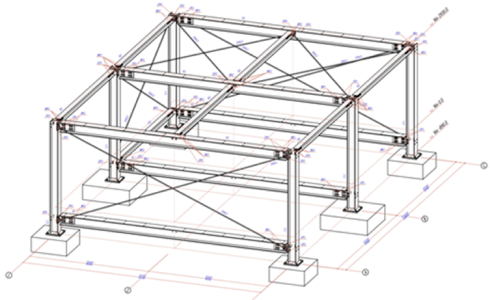
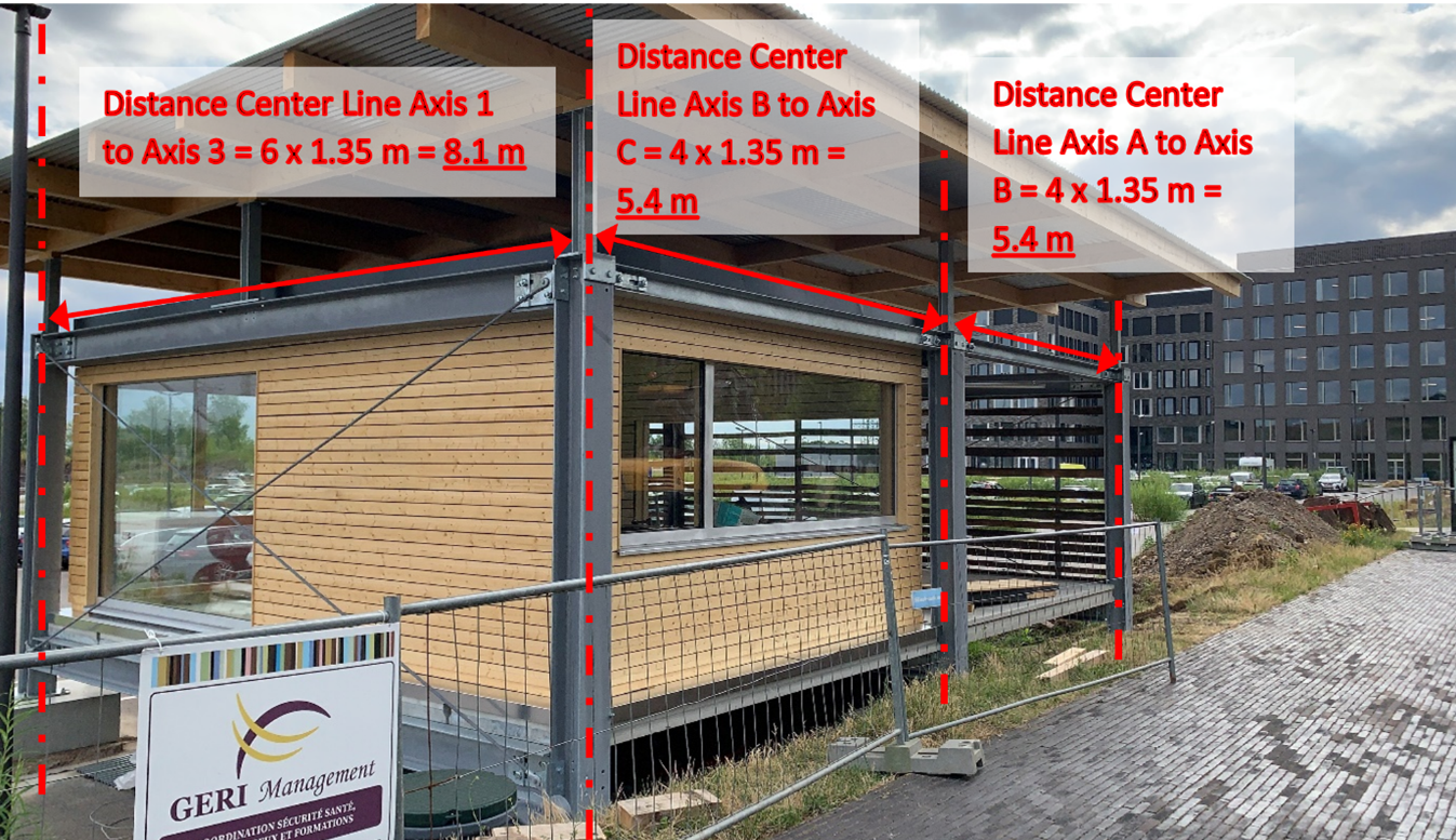
The Grid system
The chosen grid system provides an axial reference system for the skeleton of the structure. This means that the axis of the steel beams are
positioned on the grid lines, while the columns are placed in the intersection points of the grid lines.
Columns and other vertical elements, which are of structural
and load bearing nature, are allowed only to be arranged at
the intersection points of the grid lines, which have a
spacing of 1.35 m.
The use of an axial reference system would result in overlaps
between the columns and the beams at the intersection of the grid lines. Usually, this is solved by cutting the beam with millimetre exactitude to fit between the columns. This also implies that the exact length of the beam depends on the size of the column.
This is solved by using a standardized nominal beam length L = n x 1.35 – 2 x 0.23 m, so the distance between the centreline of a
column to the end of an adjacent beam is fixed to 230 mm. The
remaining gap is bridged by the adjustable L-shaped connection
pieces with long slotted holes.
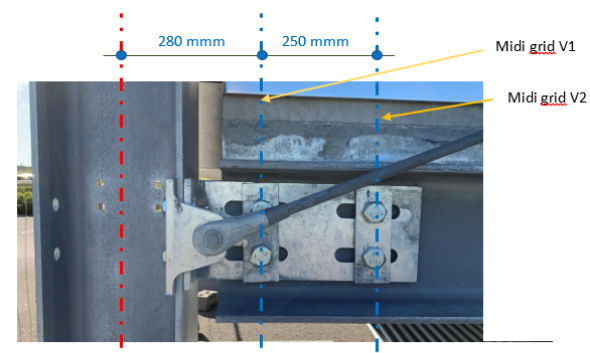
The bolts are only allowed to be placed on two vertical lines with a
distance of 280 mm between the maxi grid and midi grid V1 and 250 mm between midi grid V1 to midi grid V2.
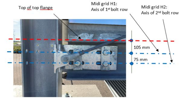
The first bolt row is placed at 105 mm under the top surface of the beam for midi grid H1. The following rows always locate at 75 mm below the upper ones for the next rows below with midi grid H2.
In order to maximize the reuse potential, the need for remanufacturing in a potential reuse scenario should be minimized because that
implies additional work (meanly cutting and drilling) and the acceptance for reuse is reduced with each further manipulating step. This was
achieved by having.
- Standardized element dimensions
- avoiding welds
- Providing pre-drilled holes in the midi-grids.
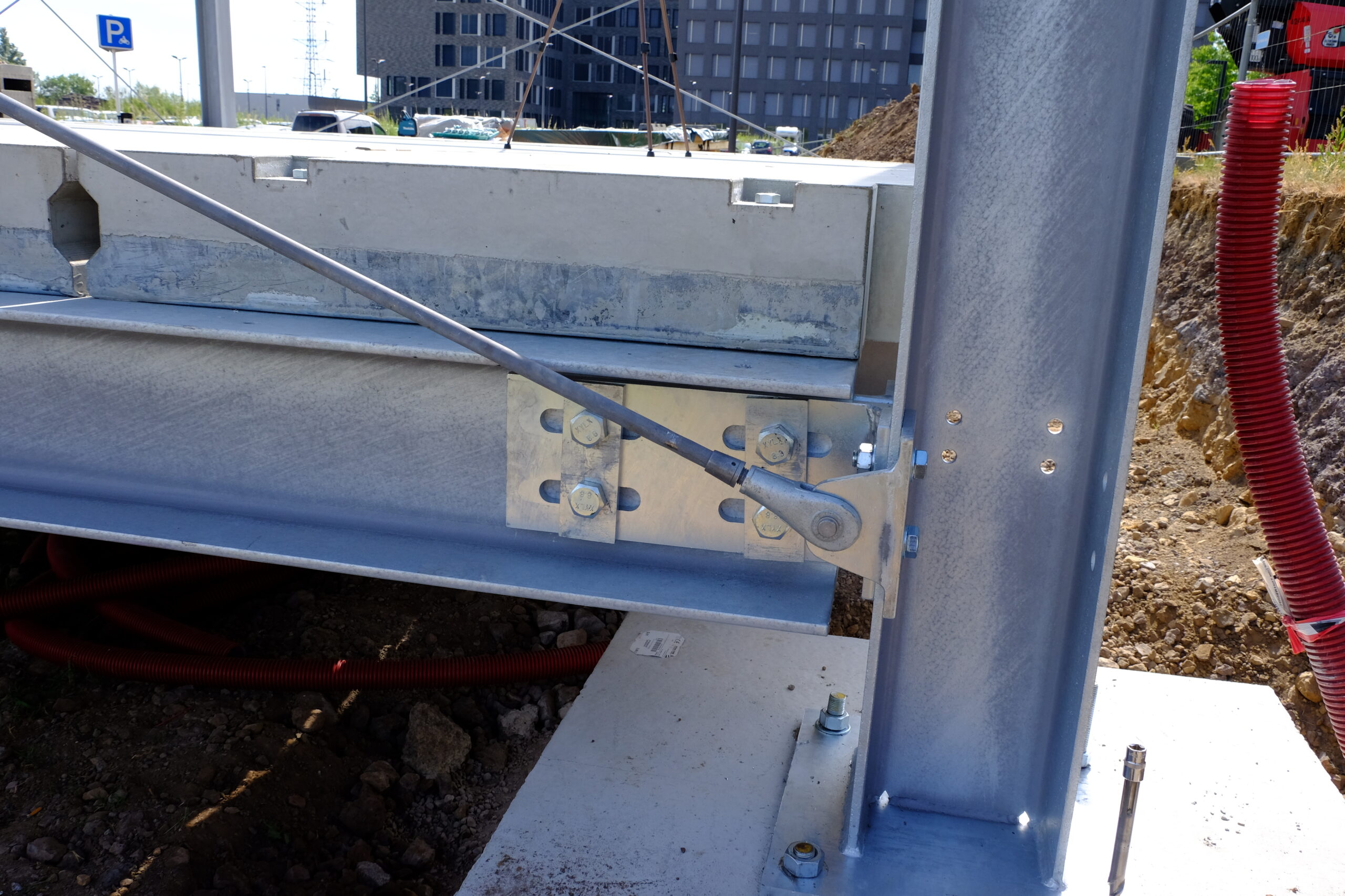
All of these points are interrelated. Using a carefully chosen system of pre-drilled holes in standardized distances from each other (midi grids), the use of plates welded to the columns becomes unnecessary.
Hereunder you can find examples of of the tie bars of the cross-bracing connected to the beams and columns without additional
manufacturing at steel beam or steel column. These connections use the already existing pre-drilled holes in the column flanges as the
beam-to-column connections.